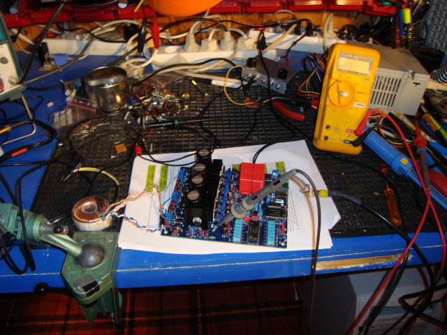
This is the testpage for my first DAC build.
I had to split the evolution pages of this DAC. This is my test
presentation page for this DAC.
Then I have the modification page where I listen and also do THD
tests with PC and soundcard. That's
on another page.
Anchors on this page, and in following order:
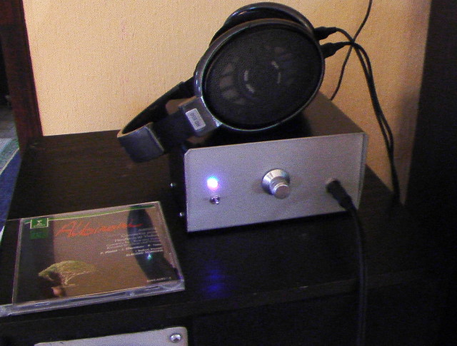
This is my first DIY headphoneamplifier i did 2 years ago. I got very good help and learned alot from the DIY audio forum member Nico Ras. It's a class A amplifier with very high bandwith. The headphones is, hands down, the best there is for the money I would say. They are also very good for OTL tubeamps because they have 300 ohm impedance which make it easier to drive. I use them in my livingroom for my second DIY headamp, with tubes.
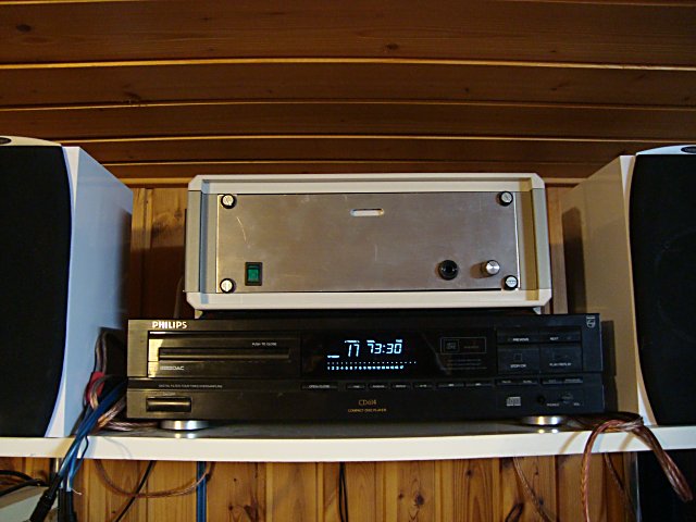
I use this old Philips player as the CD
transporter and use the SPDIF to my DAC's input receiver, which
is the Crystal CS8412. It has one of the better transports and
is also a spare part for my Marantz
CD65II. The CDM4/19. The player has a A-B button which you
can use to repeat snippets. Perfect when you want to do long tests
with the test CD i have made. It's also good for practising the
guittar and want to copy that Eric Clapton lick exactly right.
I bought it for 1.5 $ at an Internet auction. Good deal don't
you think?
The amp on top of the player is another DIY project, the Kleinsmidt 10A.
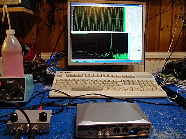
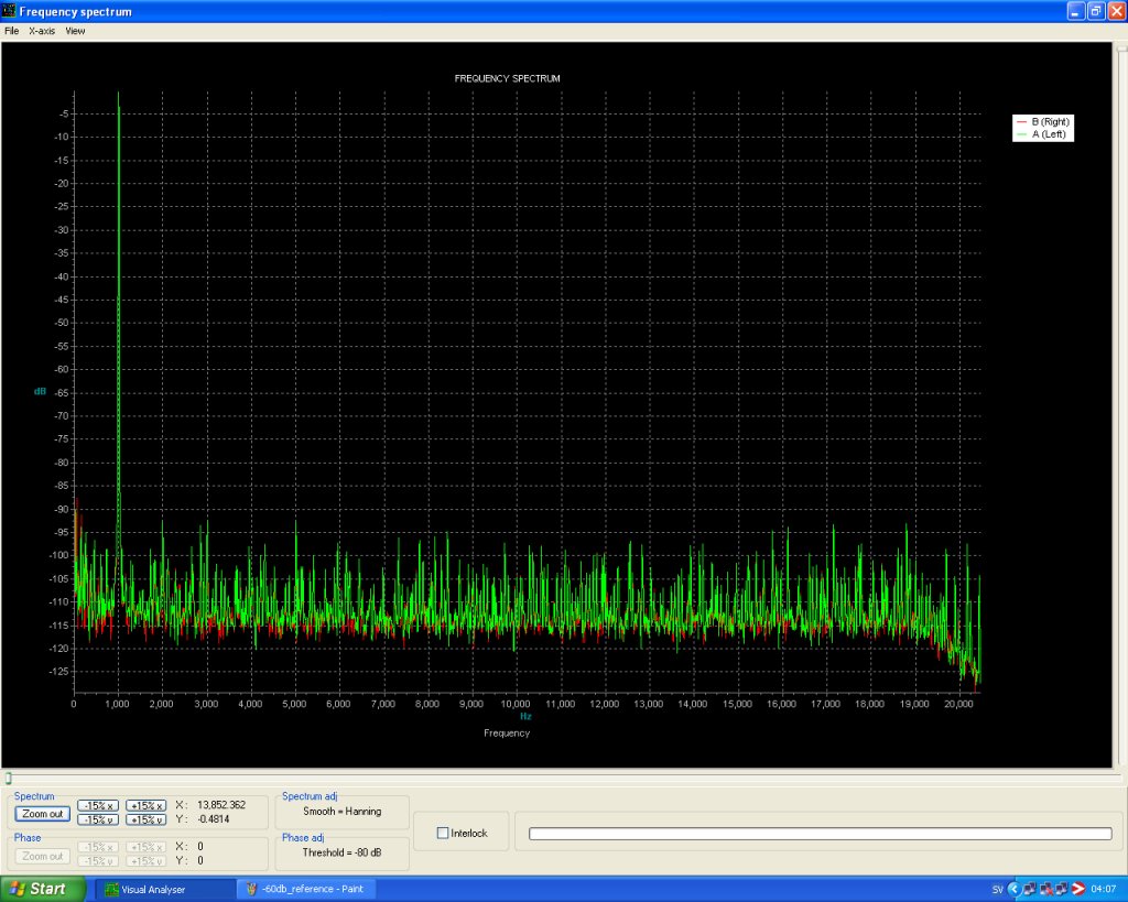
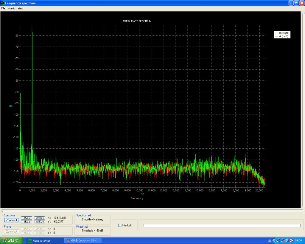
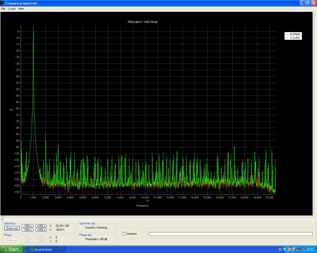
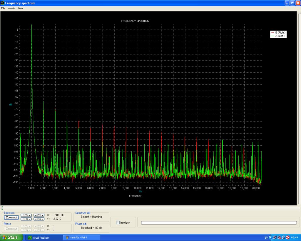
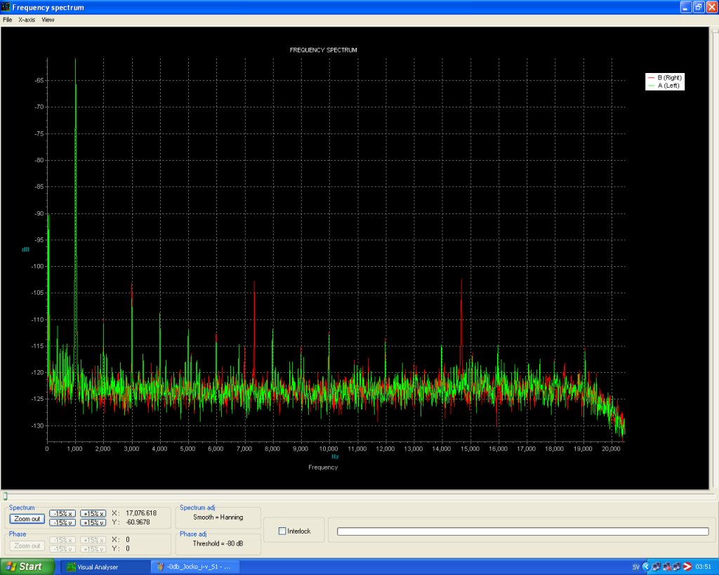
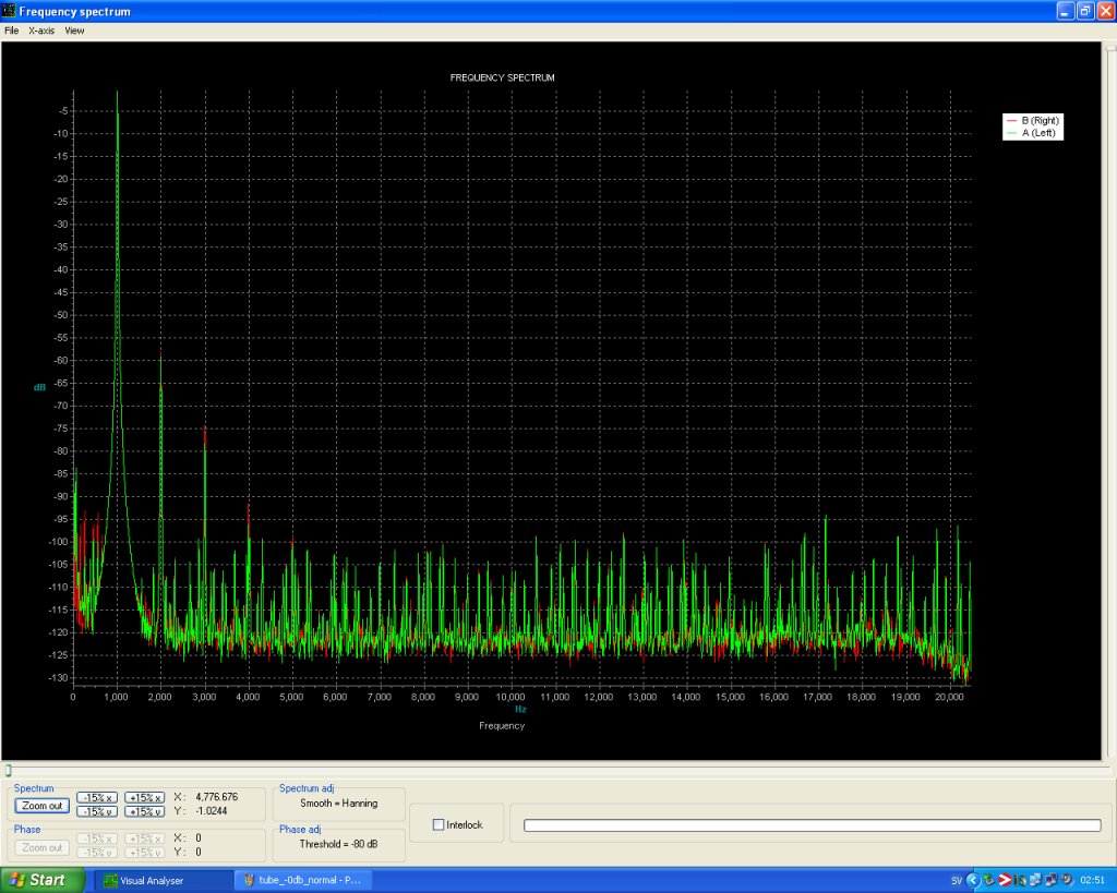
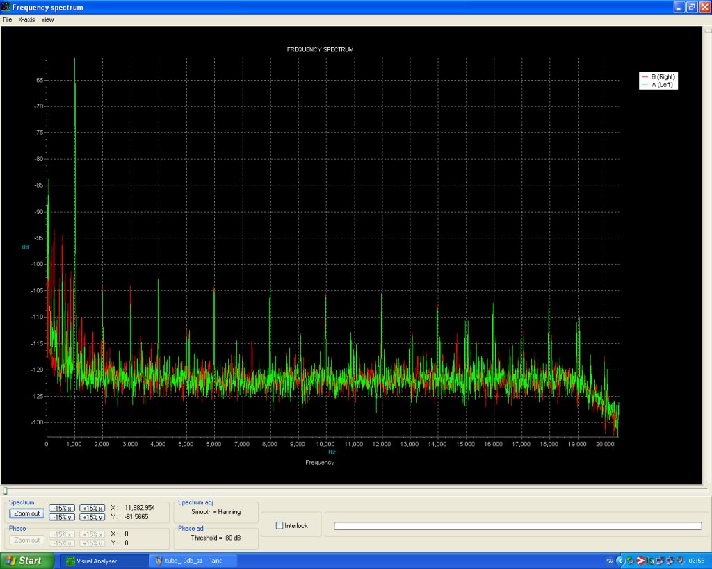
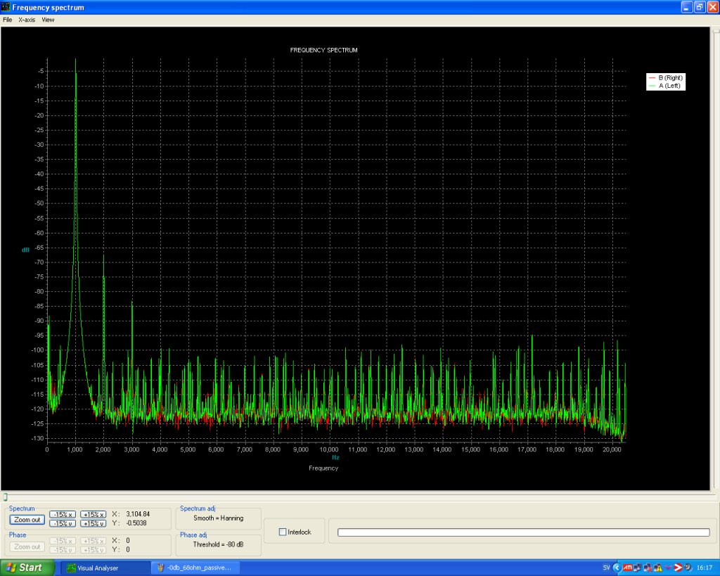
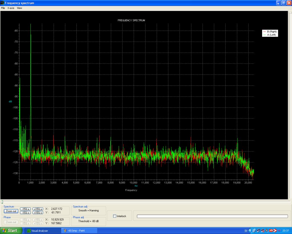
These days we have computers to do nice FFT measurings. This is what I use. Sometimes I also use the Rmaa software for amplifier testing. Picture above is DUT for one channel of the tubed I/V amplifier later down this page. Below is the reference for this setup. The first graph show worse numbers then it is on the measurings futher down because I had to use the inbuilt amplifier in my measuringe interface. But the scopecables and cheap RCA phono and linecables are the same as in the tests below. The second graph, -60dB is exactly how it's setup but without the tested DAC. I'm not telling you this is the best test setup in the world but it gives a good hint on whats going on and you could also compare the different approaches for the I/V stages on this page. The two CD signals i got from Pedja Rogics site and burned on a plain CD.
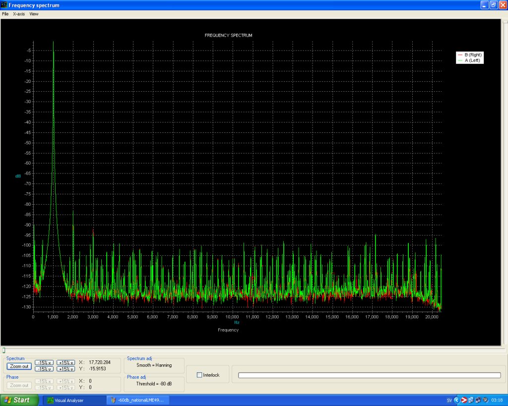
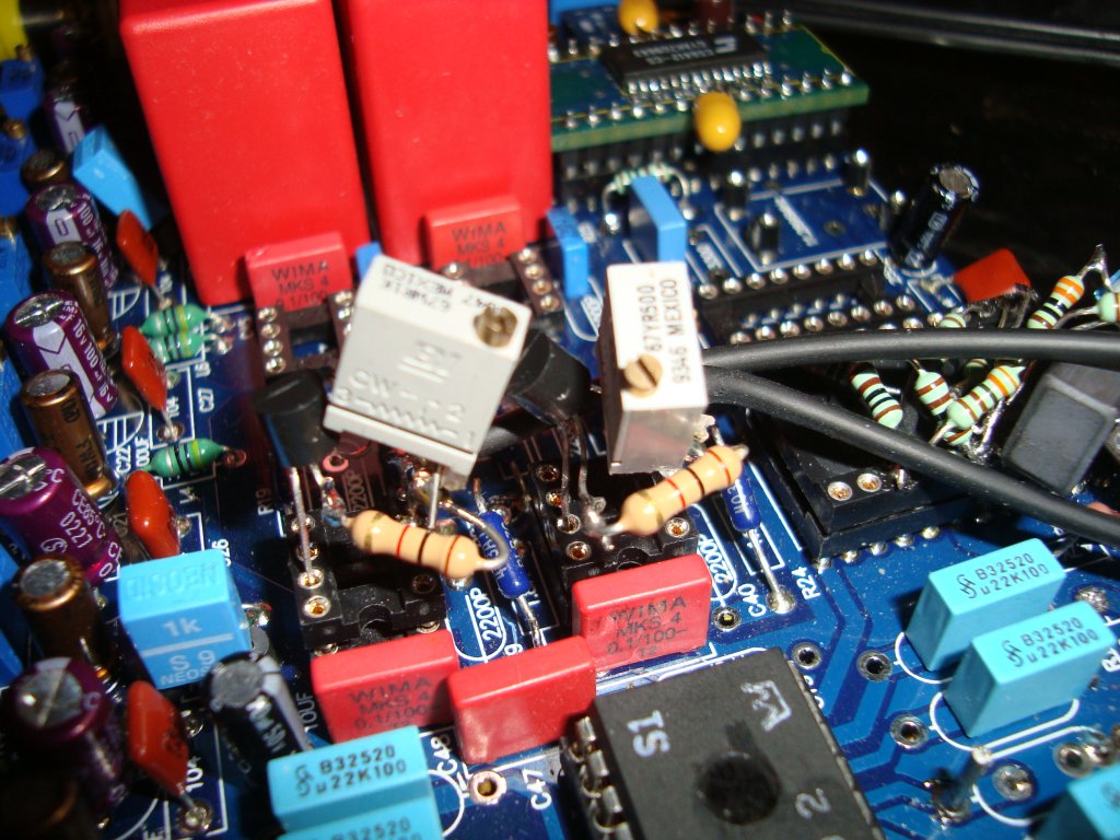
After I brought this kit up on the bench again I was eager to test out the new National Semiconductors LME49710 OP's I got together with an old TDA1541 S1 grade from Audioman54 at DIY audio forum. That was early 2009 but this moment have been left aside until now.
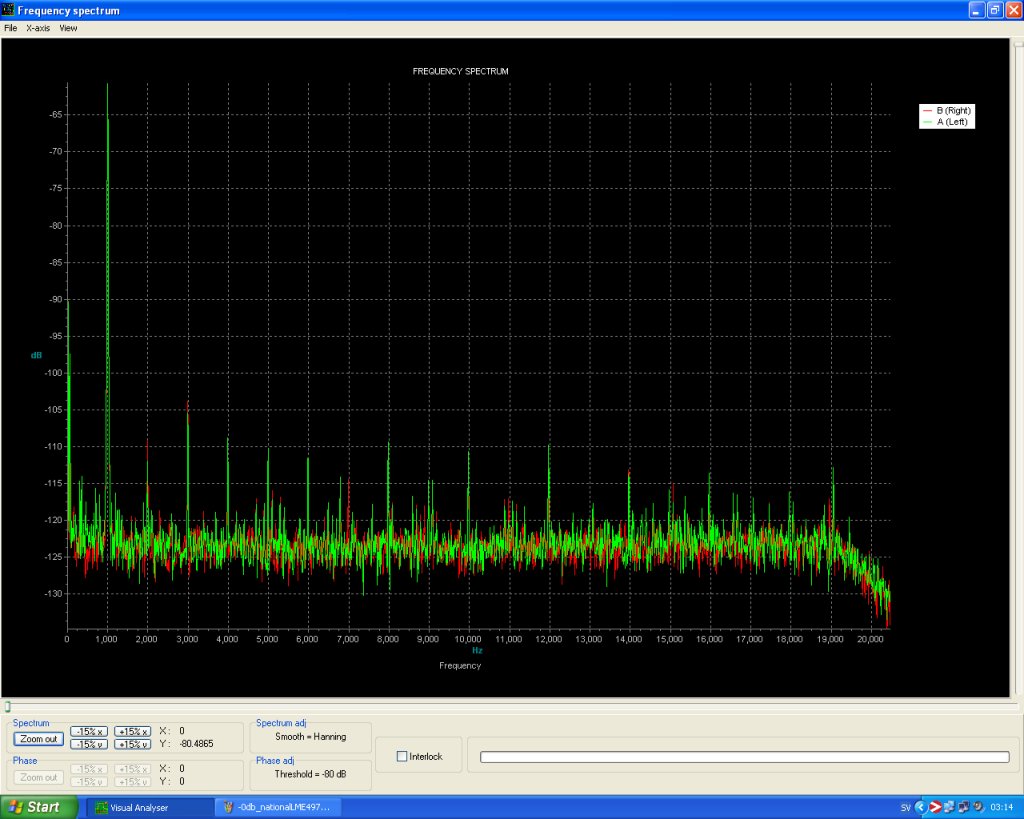
There is definately small differences in sound between OP's even if they have the same THD figures and under the same conditions. The graphs below for measuring of two of the manufacturors OP gives the thought that they are the same captured graphs. But they arent. So when it comes to measure differences between two high grade OP's the method I use will not show any.
I use well filtered regulated PS to the OP's. A 1mH in serie with two ferrite pearls and one 10uF tanthal at each + - voltage near the OP's. This is done on top of the kit's LM317 regulator allready well done PSU. The environment should therefore be OK for this OP's and if it would all be only about the distortion I think we could say they all would sound the same. But I have learned the last two years that it's not only about distortion. Maybe something about feedback and other unknown things makes certain circuits sound different even if they have the same THD figures.
My own, very subjective, listening tests with the few, considered, high grade OP's gives:
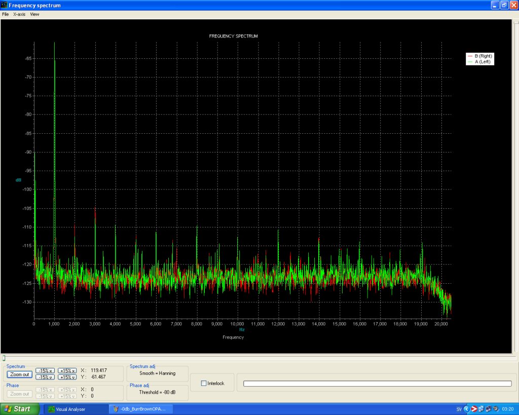
Burr Brown OPA627 vs. National LME49710 in the I/V stage place: OPA seems to give more slam and punch but also a bit darker and harder sound. Good dynamics. The LME's is more backless and have more highs and maybe dissolves the instruments slightly better. But maybe less more punch and dynamics.
I also tested with the Analog Devices AD797 and thought it was very "analog" sounding and had punchy bass but also less upper highs. All in all very small differences. Also different OP's at the buffer place was hard to tell and it takes time to finish such tests. Sometimes it's good to listen to known music a lot for some days before you switch parts and listen to the same known music again. It's in it's nature difficult to do A-B tests with this kind of tests. If you will evaluate this DAC you have to switch the OP's and then listen again. If you have built two exact copies maybe you can feel confident in A-B tests if you first have them judged and listened to, so that there is no difference between the two copies before you start shifting parts.
The two pictures, for each OP, below shows the distortion figures at 0dB and -60dB from a FFT graph. The right channel is slightly worse on all measurings and I discovered that after all was done. I found the cause to be my testpoint soldered in on one of the decoupling legs of the TDA1541. The testpin was used to measure when I tried another mod. The DEM reclocking. Sorry for that but the figures are anyway comparable and interresting. The reference FFT graphs is shown after my description of my used reference equipment for this page listening and measuring tests on top of this page.
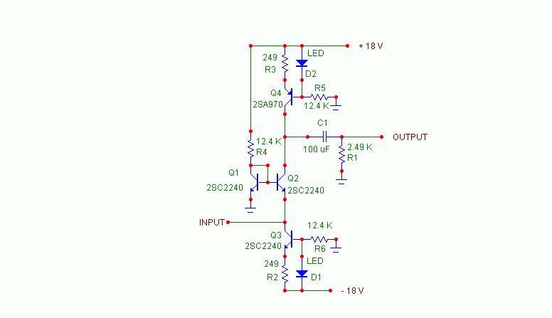
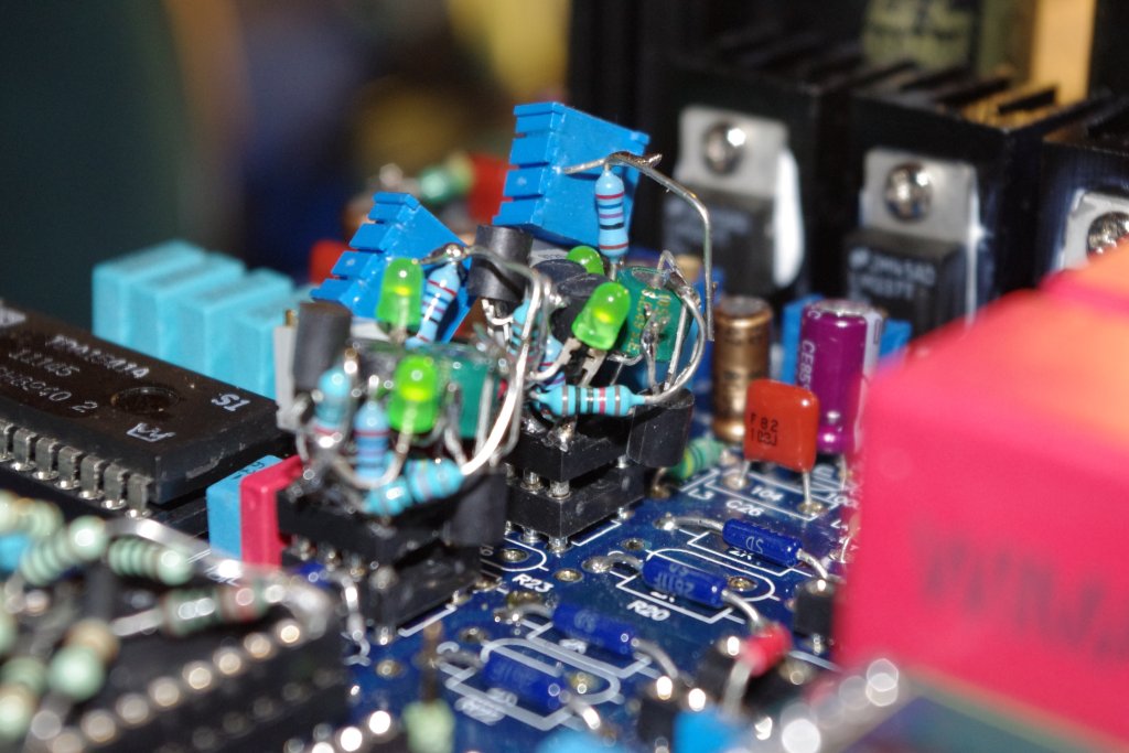
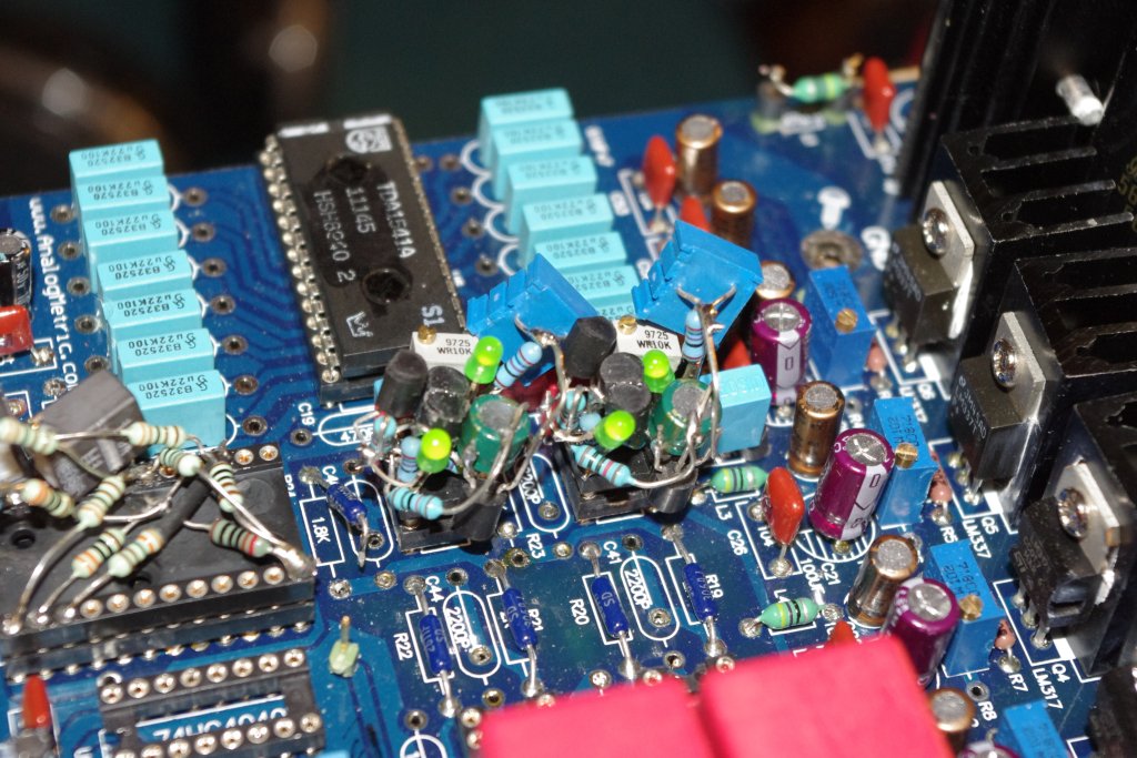
This little project was fun to test. I managed
to do two of this with my brain surgery fingers . All components
fitted on IC holders, including a pot at R4 and a pot parallelled
over R3, so that I directly could replace the first IC. Schematic
is from the first post at DIY Audio of the former member Jocko
Homo. He is now a moderator of another good forum, the DIY HiFi
forum.
It's a teaser and there is long discussions and no practical building
in that thread (as often IMHO). A lot of armchair talk and simulations
which with this circuit has problems. I am chiming in at post
#182 several years later.
I took me the time to really try it as it
is and it works really well exept it's very sensitive to adjust
the right working point between the collectors of Q4 and Q2.
I used other component values though. I use 270 ohm on R3 and
R4. 10k pot on R4. R5 and R6 are 10k. R1 4.7k and C1 47uF. Green
LED's. Transistors are BC546B and BC557B. I have selected them
to HFE around 280 to 290. Q1 and Q2 are glued to each other. It
didn't work at all before I parallelled R3 with a pot on 1k ohm.
I adjust it for least distortion (1khz test CD).The voltage on
Q2 collector then settles on about 8.6 V. The 10k pot at R4 is
maxed out and that gives around 0.3mV at the DAC's outputs.
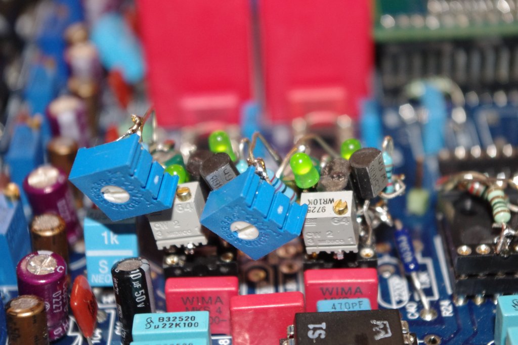
Heres some pictures from this project and testings
The two pictures below shows the distortion figures at 0dB and -60dB. The right channel is slightly worse on all measurings and I discovered that after all was done. I found the cause to be my testpoint soldered in on one of the decoupling legs of the TDA1541. The testpin was used to measure when I tried another mod. The DEM reclocking. Sorry for that but the figures are anyway comparable and interresting. The reference FFT graphs is shown after my description of my used reference equipment for this page listening and measuring tests on top of this page.

There are a lot of testgraphs below for my tubecircuit, showing the progress from my modification and test page for this DAC. I have to get it in order here so you see the evolving progress. If you read along and look at the figures and graphs below you will follow my findings for this CCDA circuit of mine.
The first two pictures below shows the distortion figures at 0dB and -60dB without compensating the offset at -66mV at the DAC's output pins. The right channel is slightly worse on all measurings and I discovered that after all was done. I found the cause to be my testpoint soldered in on one of the decoupling legs of the TDA1541. The testpin was used to measure when I tried another mod. The DEM reclocking. Sorry for that but the figures are anyway comparable and interresting. The reference FFT graphs is shown after my description of my used reference equipment for this page listening and measuring tests on top of this page.
If you think that the K2 THD -60dB at the
signal of -0dB is to much to bear, so rethink. It's a second order
distortion in harmony with the testing frequency at 1000Hz and
it's only about 0.1 THD. Also I don't know any music playing at
-0dB all the time even if we are beginning to get there with the
todays overcompressed music. Who needs a new Music system after
the CD when the producers only use 6dB dynamics when there is
at least 85 dB in practice to get out of the CD format. And again
... Low distortion figures at low levels is the way to go to use
all the bits there are in the CD format.
(10 feb 2010. There will be more enhancement read on. The
lowest THD figures are yet to come ;-)
My "second approach", without positive feedback, of this circuit and also the double DAC arrangement gave way better FFT graphs.
And this -66mV at the outputs of the DAC ? Sollution is below. Even lower THD.
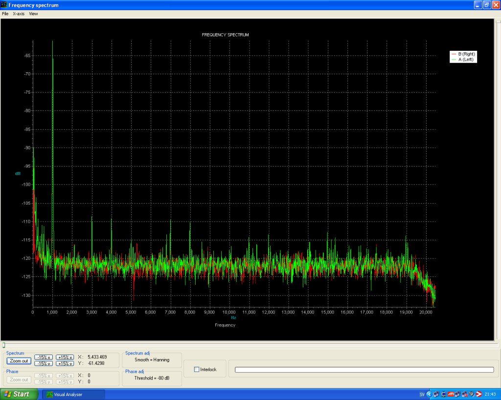
This last measuring capture, -60dB picture below, shows another one of my findings, with compensation for the -66mV at the I/V resistor. Done with a JFET CCS. I use the one called the "Pedja style" at the DIY Audio forum. Much better isn't it? About 45 dB below signal for K3, K4, K7 and K8 is better then the typical spec for TDA1541A ! The rest is even far lower. And again .... low distortion figures at low levels is the way to go to use all the bits there are in the CD format.
Then with the double TDA's piggybacked and also the second approach of this circuit without the positive feedback.
Yes it looks better even though there are
a few dB higher rubbish (-110 to -105dB) in the lower part around
500Hz on the -60dB chart. The 50Hz hum at about 87dB below is
anyway the major disturbance. I will lose some of that when I
use a better PSU for the tubestage. You can be sure of that. Please
compare this last graph with the two -60dB ones from the
OP measurings above. Astonishing isn't it?
updated 4 feb 2010. I have now done some loving massage
for my OP's as well. Lower output comparabe to the latest tubesetup
below, the one with E88CC. I then got really low THD figures from
the SS parts as well. Pictures of graphs not yet at hand above.
The competing continues
From this DAC's modification and testing page you can follow in more detail whats in the pipe of progress. So next picture shows use of the tube E88CC and lower amplification but "calibrated" for balance and the "sweet spot" of load where this circuit shines the best.
bmp.jpg)
Best so far!
Still more to come. This page will be more uncluttered when I'm finished with my setup.